UDP5040-40 400W 40V/40A Programmable DC Switching Power Supply
UDP5040-40 400W 40V/40A Programmable DC Switching Power Supply
Overview
The UNI-T UDP5040-40 is a single-channel 400W programmable DC switching power supply delivering 0–40V and 0–40A with auto-ranging across the rated power envelope. It pairs a wide output range with the regulation accuracy, source-emulation and remote control expected of a professional programmable supply.
Voltage accuracy is ±(0.05% of set + 0.05% of rated) and current accuracy ±(0.5% of set + 0.1% of rated); ripple is held to 50mV p-p with a 100 ppm/°C temperature coefficient. A 2.4-inch TFT-LCD shows voltage, current and power together, and full SCPI control over USB and LAN drops the UDP5040-40 straight into LabVIEW, Python-VISA or any ATE framework.
Choosing Your Model — UDP5000 Series
The UDP5000 name spans 20 models built on one platform: five voltage classes (40 V / 80 V / 160 V / 250 V / 800 V) across four power classes (400 W / 800 W / 1200 W / 2000 W). They differ only in output range and chassis size — control, accuracy, protection and interface are otherwise identical. Compare the full series before selecting:
| Rated Power | 40 V | 80 V | 160 V | 250 V | 800 V |
|---|---|---|---|---|---|
| 400W |
UDP5040-40 0–40A |
UDP5080-20 0–20A |
UDP5160-8 0–8A |
UDP5250-6 0–6A |
UDP5800-2 0–2A |
| 800W |
UDP5040-80 0–80A |
UDP5080-40 0–40A |
UDP5160-16 0–16A |
UDP5250-12 0–12A |
UDP5800-4 0–4A |
| 1200W |
UDP5040-120 0–120A |
UDP5080-60 0–60A |
UDP5160-24 0–24A |
UDP5250-18 0–18A |
UDP5800-6 0–6A |
| 2000W |
UDP5040-200 0–200A |
UDP5080-100 0–100A |
UDP5160-40 0–40A |
UDP5250-30 0–30A |
UDP5800-10 0–10A |
Every model shares the same chassis architecture, control system, regulation accuracy, protection suite, and interface set. The 800 V UDP5800 tier does not support series connection; all other tiers support series and parallel combining. Choose by the voltage class that covers your rail and the power class that covers your load — output range and chassis height scale with power, the instrument does not change.
Key Features
- 400W / 0–40V / 0–40A — auto-ranging across the rated power envelope
- Voltage accuracy ±(0.05% of set + 0.05% of rated); current accuracy ±(0.5% of set + 0.1% of rated)
- Low ripple — 50mV p-p voltage, 80mA rms current (20 MHz BW)
- CC/CV priority slope modes — choose voltage-first or current-first turn-on for DUT safety
- Adjustable internal resistance to 1.000Ω — emulate batteries, fuel cells and solar sources
- List Mode — 128 programmable V/I/dwell steps, 1 to 9,999, infinite cycles, stand-alone
- Front and rear output terminals (front limited to 10 A)
- Multi-unit series/parallel — up to 4 parallel / 4 series
- USB + LAN with full SCPI 1999.0 / IEEE-488.2; 2.4-inch TFT-LCD
- Discharge-load control for rapid output bleed-down
UNI-T UDP5040-40 Details

CC/CV Priority — Protect the Device, Not Just the Supply
Most bench supplies treat the CC/CV crossover as a fixed hardware behaviour. The UDP5000 lets you choose which parameter takes priority at turn-on and during mode transitions. CV-priority establishes the target voltage first — the right choice for microcontrollers, FPGAs and analog rails. CC-priority brings current up under control — the safer choice for LEDs, laser diodes and battery charging where inrush must be bounded.
CC/CV priority mode transition behaviour
Adjustable Slew Rate — Control How Fast Power Arrives
Voltage and current slew rates are independently settable. A slower ramp prevents inrush into capacitive loads, reduces mechanical stress on motor windings at start-up and gives sensitive analog circuits time to settle; the high-speed default mode is there when fast settling is what the test needs.
 Adjustable voltage and current slew rate

Internal Resistance — Simulate Real Power Sources
The internal variable-resistance function (set in CV mode, up to 1.000Ω in 1 mΩ steps) makes the terminal voltage droop with load current exactly as a battery, fuel cell or solar panel would — no physical resistor, no thermal risk, value changeable instantly from the panel or over SCPI.
Internal variable resistance source emulation
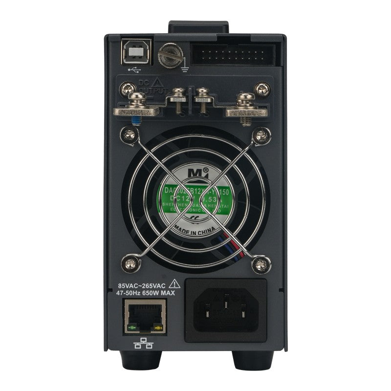
Front & Rear Outputs — Bench-Ready and Rack-Ready
Output terminals are provided on both panels. Front terminals are there for quick prototype hookup; rear terminals keep permanent rack wiring clean. Both are the same single output — front-panel draw is limited to 10 A, so high-current loads belong on the rear.
 Front and rear output terminals

List Mode & Discharge Control — Automate Output Sequences
List Mode runs up to 128 programmed V/I/dwell steps for 1 to 9,999, infinite cycles or continuously, stored locally or exported, executing with no PC attached — built for overnight burn-in, charge-profile runs and production routines. The internal discharge load bleeds output capacitance down rapidly when output is switched off.
List Mode programmable output sequencing
Multi-Unit Operation — Scale When You Need More
Up to 4 identical units parallel for more current, or up to 4 series for more voltage, coordinated over the rear CAN / LS_BUS interface from the master unit or a single SCPI connection; unit-to-unit balance stays within ~5% of rated.
 Multi-unit series and parallel operation

Display and Control
A 2.4-inch TFT-LCD presents voltage, current and power simultaneously with a concise multifunction keypad; external analog control (0–10 V setpoint plus digital ON/OFF) is available on the rear analog interface for closed-loop and HIL setups.
UDP5000 front panel — 2.4-inch TFT-LCD with multifunction keypad
Applications
Battery and Energy-Storage Test
The wide 0–40 V range covers 12 V to 36 V lithium-ion and LFP packs used in e-bike, power-tool and light-EV work. Internal-resistance emulation and List Mode let you reproduce charge profiles and varying pack states without cycling real cells.
New-Energy and Automotive Electronics
DC/DC converter input stages, inverter front ends and sub-40 V automotive ECUs benefit from the tight regulation, low ripple and CC/CV priority control.
Automated Test and Production
SCPI over USB or LAN plus stored List Mode sequences make the UDP5000 a clean fit for unattended characterisation, burn-in and end-of-line test.
Accessories and Family Options
In the box: power cord (destination-country standard, 1.8 m), four-conductor analog-interface flat cable (3.5 m), USB cable (1.5 m), M3 mounting screws, output-terminal protection cover, and rack distribution bracket.
The UDP5000 series spans 16 models on one platform — see Choosing Your Model above for the full voltage × power matrix if a different rail or load fits your application better.
Frequently Asked Questions
Can I use the front and rear output terminals at the same time?
Both terminal sets are parallel connections to the same single output. You can wire both, but the front terminals are limited to 10 A maximum — route high-current loads to the rear panel.
What is the difference between the VHS/IHS and VSR/ISR slope modes?
VHS (CV high-speed) and IHS (CC high-speed) use the supply's default fast rise and fall rates. VSR (CV slope) and ISR (CC slope) let you set the rise and fall rate so output ramps in controlled fashion — useful for capacitive and motor loads, and for sensitive analog circuits that need settling time.
Does the internal-resistance function need an external resistor?
No. The internal variable-resistance function electronically emulates source impedance (set in CV mode, up to 1.000Ω in 1 mΩ steps), so the supply behaves like a battery, fuel cell or solar source with no physical resistor and no added thermal risk.
Can multiple units be combined for more power?
Yes. Identical models combine for more current (parallel, up to 4 units) or more voltage (series, up to 4 units), controlled from the master unit or a single SCPI connection; unit-to-unit balance stays within ~5% of rated.
How does it integrate with automated test?
USB and LAN with full SCPI 1999.0 / IEEE-488.2 support LabVIEW, Python-VISA and any standard ATE framework; List Mode runs stored sequences stand-alone without a connected PC.
Specifications
| Model | UDP5040-40 |
| Output Channels | 1 (single channel) |
| Rated Output Voltage | 0–40V |
| Rated Output Current | 0–40A |
| Rated Output Power | 400W |
| Maximum Adjustable Voltage | 42V |
| Maximum Adjustable Current | 42A |
| Voltage Setting Resolution | 1mV |
| Current Setting Resolution | 1mA |
| Voltage Display Resolution | 1mV |
| Current Display Resolution | 1mA |
| Voltage Output Accuracy | ±(0.05% of set + 0.05% of rated) |
| Current Output Accuracy | ±(0.5% of set + 0.1% of rated) |
| Voltage Load Regulation | ±6mV |
| Voltage Line Regulation | ±6mV |
| Current Load Regulation | ±13mA |
| Current Line Regulation | ±6mA |
| Voltage Ripple (p-p, 20 MHz BW) | 50mV |
| Voltage Ripple (rms) | 5mV |
| Current Ripple (rms) | 80mA |
| Rise Time (rated load) | <50ms |
| Fall Time (rated load) | <50ms |
| Fall Time (no load) | <500ms |
| Adjustable Internal Resistance (max) | 1.000Ω |
| Remote Sense Compensation (max) | 1.5V |
| Temperature Coefficient | 100 ppm/°C |
| Preset Memory Groups | 32 |
| List Mode Groups | 128 |
| List Mode Step Time | 0.1s to 99,999.9s |
| List Mode Cycles | 1 to 9,999, infinite |
| Max Series-Connected Units | 4 |
| Max Parallel-Connected Units | 4 |
| Protection | OVP, OCP, FOCP, OTP, Power Limit, Watchdog, Output ON/OFF Delayer |
| Remote Interface | USB-Device, USB-Host, LAN, Analog I/O |
| SCPI / IEEE-488.2 | Yes (SCPI 1999.0 + IEEE-488.2) |
| AC Input Voltage | 85-265 Vac |
| AC Input Frequency | 47-63 Hz |
| Efficiency (typ) | 75% |
| Power Factor | 0.99 @100Vac, 0.97 @200Vac |
| Display | 2.4in TFT-LCD |
| Cooling | Fan-forced air cooling |
| Operating Temperature | 0°C to +50°C |
| Operating Humidity | 20% to 85% R.H. (non-condensing) |
| Storage Temperature | -20°C to +60°C |
| Max Altitude | 2000m |
| Weight | 3kg |
| Certifications | CE |
Documentation
Options & Accessories
Included in box:
- Power cord
- English download guide
- multi-language safety manual
- calibration report (COC)
无法加载取货服务可用情况
现货
查看完整详细信息